Understanding the Wiring Diagram for CM Lodestar: A Comprehensive Guide
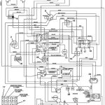
Wiring Diagram Cm Lodestar
contributor by : William Taylor
If you’re working with a wiring diagram for a CM Lodestar, you might find yourself looking for a clear and concise guide to help you navigate the complexities of the system. Well, look no further! In this article, we’ll break down the wiring diagram for the CM Lodestar in simple, easy-to-understand terms. We’ll cover everything from the basic components to the more intricate connections, so you can feel confident in your understanding of this essential piece of equipment.
another content from contributor : 2002 bmw e46 s54 m3 wiring diagram
Understanding the Wiring Diagram for CM Lodestar
The CM Lodestar is an essential piece of equipment for many applications, and understanding its wiring diagram is crucial for its proper functioning. In this article, we’ll break down the wiring diagram for the CM Lodestar in simple, easy-to-understand terms. We’ll cover everything from the basic components to the more intricate connections, so you can feel confident in your understanding of this essential piece of equipment.
Components of the CM Lodestar Wiring Diagram
The CM Lodestar wiring diagram consists of several components, including the power supply, the control module, and the sensors. These components work together to provide accurate and reliable readings for various applications. Here’s a brief overview of each component:
1. Power Supply: The power supply provides the necessary voltage and current to the control module and sensors. It is essential to ensure that the power supply is properly connected and functioning correctly.
2. Control Module: The control module is the brain of the system, processing the signals from the sensors and controlling the output. It is essential to ensure that the control module is properly connected and functioning correctly.
3. Sensors: The sensors are used to measure various parameters, such as temperature, pressure, and flow rate. It is essential to ensure that the sensors are properly connected and functioning correctly.
Connecting the Components
Once you have a basic understanding of the components in the CM Lodestar wiring diagram, it’s time to connect them. Here are the steps to follow:
1. Connect the power supply to the control module.
2. Connect the sensors to the control module.
3. Ensure that all connections are secure and properly tightened.
Testing the System
After connecting the components, it’s essential to test the system to ensure that it is functioning correctly. Here are the steps to follow:
1. Turn on the power supply.
2. Check the output of the control module.
3. If the output is not as expected, check the connections and troubleshoot any issues.
Troubleshooting Common Issues
If you encounter any issues with the CM Lodestar wiring diagram, here are some common problems and their solutions:
1. No output from the control module: Check the connections to the power supply and sensors.
2. Inaccurate readings from the sensors: Check the connections to the sensors and ensure that they are properly calibrated.
3. Power supply issues: Check the voltage and current output of the power supply and ensure that it is within the specified range.
Maintaining the CM Lodestar Wiring Diagram
To ensure the longevity of the CM Lodestar wiring diagram, it’s essential to maintain it properly. Here are some tips:
1. Keep the connections clean and free of debris.
2. Check the connections regularly and tighten them if necessary.
3. Replace any damaged or faulty components immediately.
Conclusion
Understanding the wiring diagram for the CM Lodestar is essential for its proper functioning. By following the steps outlined in this article, you can ensure that your system is working correctly and maintain it for optimal performance. Remember to test the system regularly and troubleshoot any issues promptly.
Alright, so you made it to the end of this article about the wiring diagram for the CM Lodestar. I hope you found it informative and easy to understand. I know it can be a pain in the ass trying to figure out all those wires and connections, but hey, that’s why we’re here to help. So, what’s the takeaway? Well, the CM Lodestar is a pretty cool piece of equipment, and understanding its wiring diagram is crucial for its proper functioning. It’s all about the basics, man. You’ve got your power supply, your control module, and your sensors, and they all need to be connected properly. And don’t forget to test that shit to make sure everything’s working correctly. I mean, who wants a system that’s not working? That’s just a waste of time and money. So, if you’re still having trouble, don’t be afraid to reach out for some help. And hey, if you’re looking for more exclusive content, check out HERE. I promise you won’t be disappointed.
But wait, there’s more. I know what you’re thinking, “Bill, I’ve got a lot on my plate. I don’t have time to read all this shit.” Well, I get it, man. Life can be a bitch sometimes. But you know what? You’ve got to take care of your equipment if you want it to take care of you. And understanding the wiring diagram for the CM Lodestar is a big part of that. So, take a deep breath, relax, and give it a read. Trust me, it’ll be worth it. And if you’re still having trouble, just remember, there’s always someone out there who’s got your back. So, don’t be afraid to ask for help. And hey, if you’re looking for more exclusive content, check out HERE. I promise you won’t be disappointed.
Alright, that’s it from me. I hope you found this article helpful, and I wish you the best of luck with your CM Lodestar wiring diagram. And hey, if you’re still having trouble, don’t forget to check out HERE for more exclusive content. Take care, and remember, the wiring diagram for the CM Lodestar is just one piece of the puzzle. Keep learning, keep growing, and keep grinding, man. That’s all I’ve got for now. Peace out.
Keywords : CM Lodestar, wiring diagram, components, connections, testing, troubleshooting, maintenance
